Use Aussie Broadband's Framed Route on a Mikrotik Router
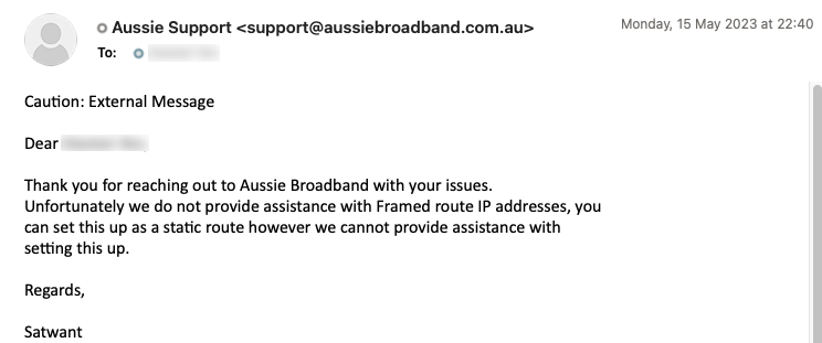
I use Aussie Broadband (which I'll refer to as "ABB") as my ISP / NBN provider and wanted an additional public IP address to allow some of my projects to have their own public facing address without any link to my main network. ABB provides these via a technique called a Framed Route. Unfortunately ABB provides no documentation or support on how to use this framed route. if you Google how to do it, you'll likely end up getting my other blog post where I tried it before, plus a few threads on Whirlpool (like this or this, but not much else).
The last time I tried this, it worked quite well using a Ubiquiti Edgerouter - but there were some limitations. First, they are expensive and hard to source; second, Ubiquiti hasn't updated the product in years and there are questions to the viability of that product line (given that their focus is now more on the Unifi line of products) and lastly there was no mechanism to provide IPv6 to a downstream router as there was no DHCPv6-PD service.
Mikrotik are a Latvian network equipment manufacturer who have been around for ages (founded in 1996) and are well known for making a robust and very full featured line of routers. They have a bit of a steep learning curve as they are extremely full featured, but their entry level producst are inexpensive and readily available. Their lowest cost devices are less than $100 and can be configured as an appliance to stick in front of your NBN "Modem" to effectively decode the Framed Route for downstream use.
I went with the Mikrotik hEX but any of their routers will work as they operated the same underlying RouterOS.
My Desired Outcome:
- No Double-NAT for either of my two networks
- Both networks fully segregated and fully accessible publicly with separate IP addresses
- Maintain full functionality of my existing UniFi Dream Machine Pro based network including Unifi Networking and Protect CCTV
- Low cost/admin "appliance" solution
- Optionally support dual stack IPv4/IPv6 across both networks
You may want to have a quick read of my previous article on this topic which goes into a bit more technical detail on how to use a Framed Route in general, this article is just a walk-through of the Mikrotik setup.
For the sake of brevity, I will assume that you have a Mikrotik that has been minimally set up per any of the many YouTube videos out there on how to do it. You should have a working WAN connection on your primary address.
I will also give these instructions via the graphical front-end. This can all be done via the command line, but I figure anyone who is skilled enough to do so will be easily able to adapt these instructions.
Step 1 - Confirm you have two static IPv4 addresses from Aussie Broadband
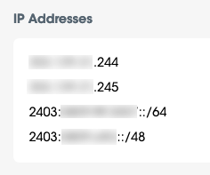
Log into your MyAussie customer portal and check the IP Addresses section which should show two IPv4 addresses and some IPv6 addresses. In my case, the top one (ending in .244) was the Frame Routed address and the bottom one (ending in .245) was the primary. The primary one will be configured via DHCP. I am not sure if ABB always shows the primary one 2nd in the list, so first let's confirm this.
Step 2 - Confirm which is the Primary and which is the Frame Routed address
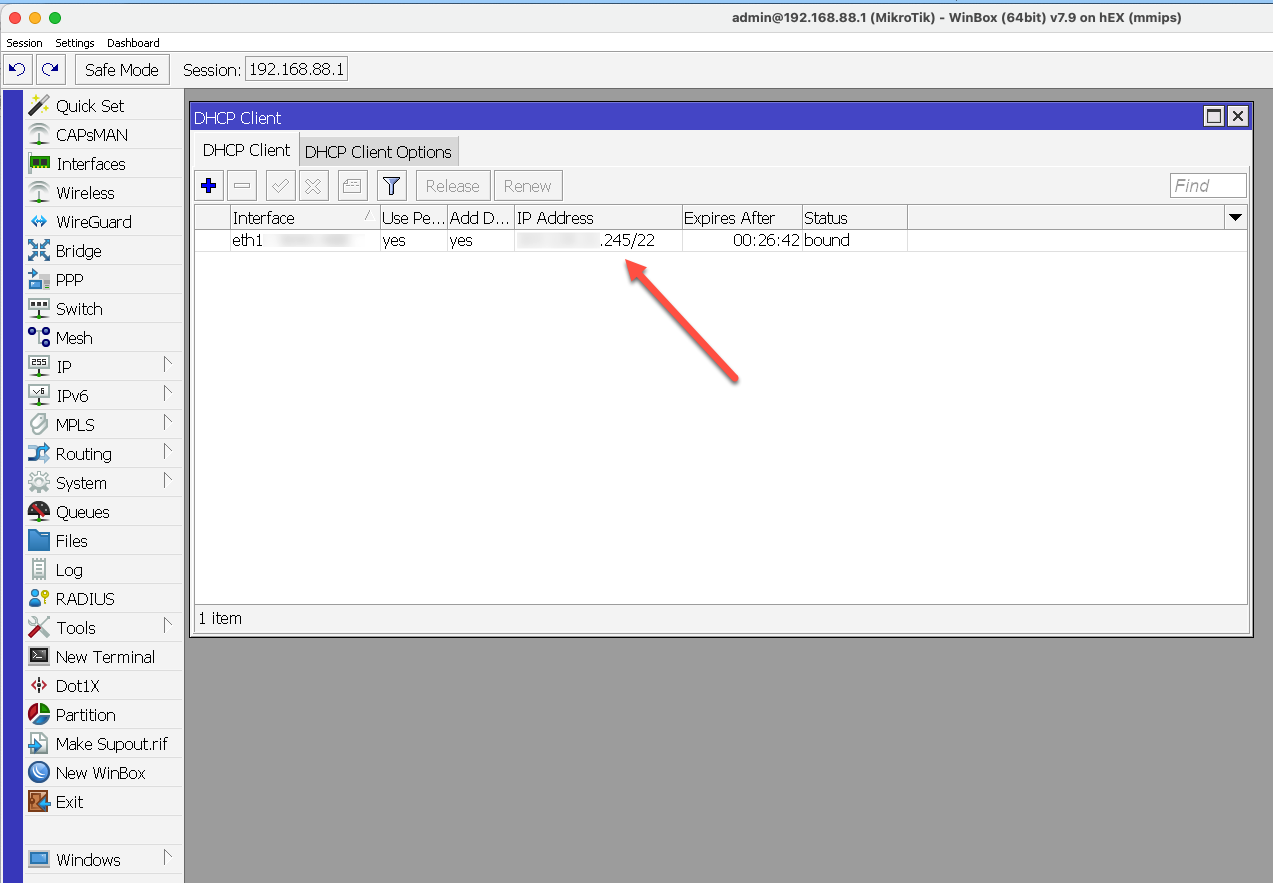
Click on the picture to enlarge. If you go to the IP -> DHCP Client section you should have already set up the DHCP Client and it will show the primary IP address there. As you can see, mine is the one ending in .245 which confirms that the address ending in .244 above is the one that is sent over the framed route.
Step 3 - Create a PPP Profile
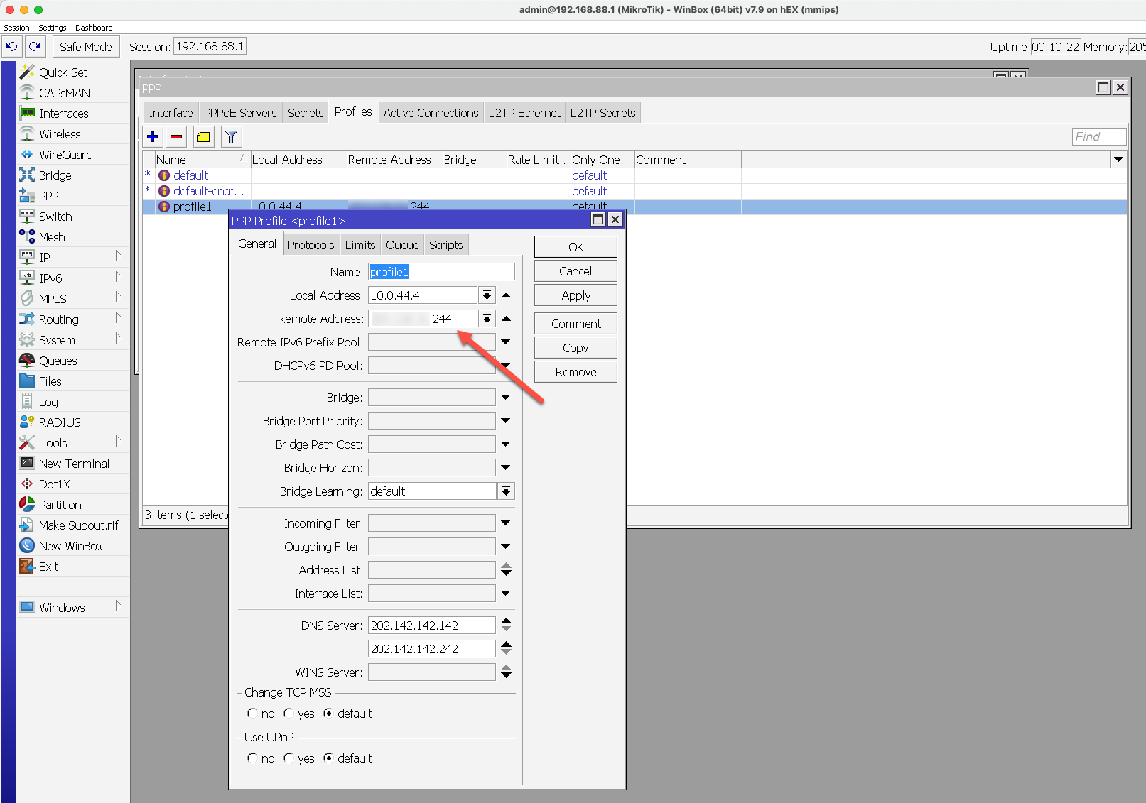
Click on the picture to enlarge. On the left menu, click on PPP which opens a new window with several tabs. First go to the Profiles tab and click on the blue + on the top left. This is to create a new PPP profile. Chose a name (here I have kept the default profile1), chose a local address (it doesn't really matter, but it should be a private address not conflicting with anything else on your network. You can probably use the same as I have if you are unsure). For Remote Address you must enter your Static Routed address that you found out in Steps 1 and 2. I also added the two ABB DNS servers, but this is optional.
Step 4 - Create a PPP Secret
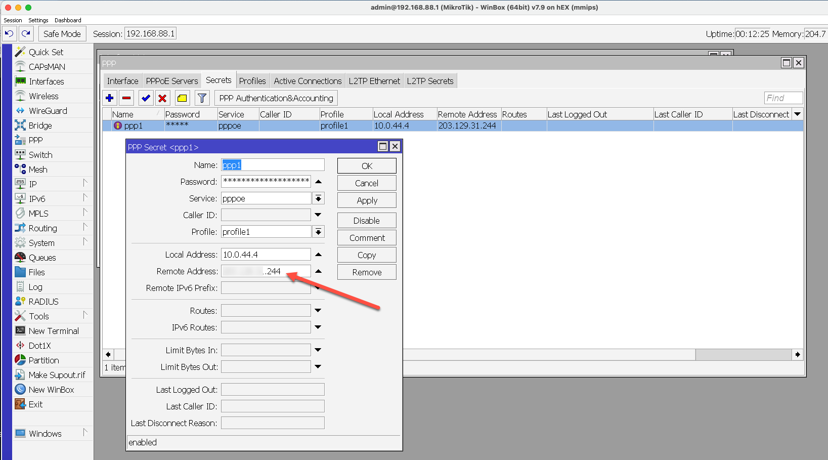
Go to the Secrets tab and create a new item by clicking on the blue + on the top left. Chose a name, a password (these will be the credentials to connect to the PPPoE connection). In the Service box you should be able to click the down arrow and find the service you created in Step 3. In the Local address section use the same local address as in Step 3 and again the Remote Address as per step 3.
Step 5 - Create a PPPoE Service
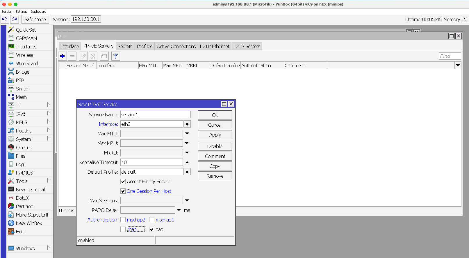
Go to the PPPoE Servers tab and create a New PPPoE Service. Give it a Name, then select the interface where your downstream device will be attached. In my case it's eth3, the 3rd Ethernet port on the Mikrotik. It could be whichever one you want, but it needs to be set up here. A good practice is to tick the "One Session Per Host" box. You can also uncheck all except the 'pap' Authentication method.
Step 6 - Create PPPoE Interface
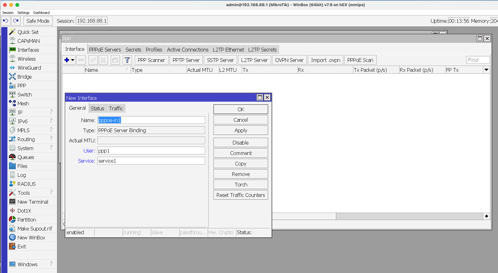
Go to the Interface tab and create a new PPPoE Server Binding interface and give it a name. The User is the one you created in Step 4. The Service is the one you created in Step 5.
Step 7 - Confirm the setup
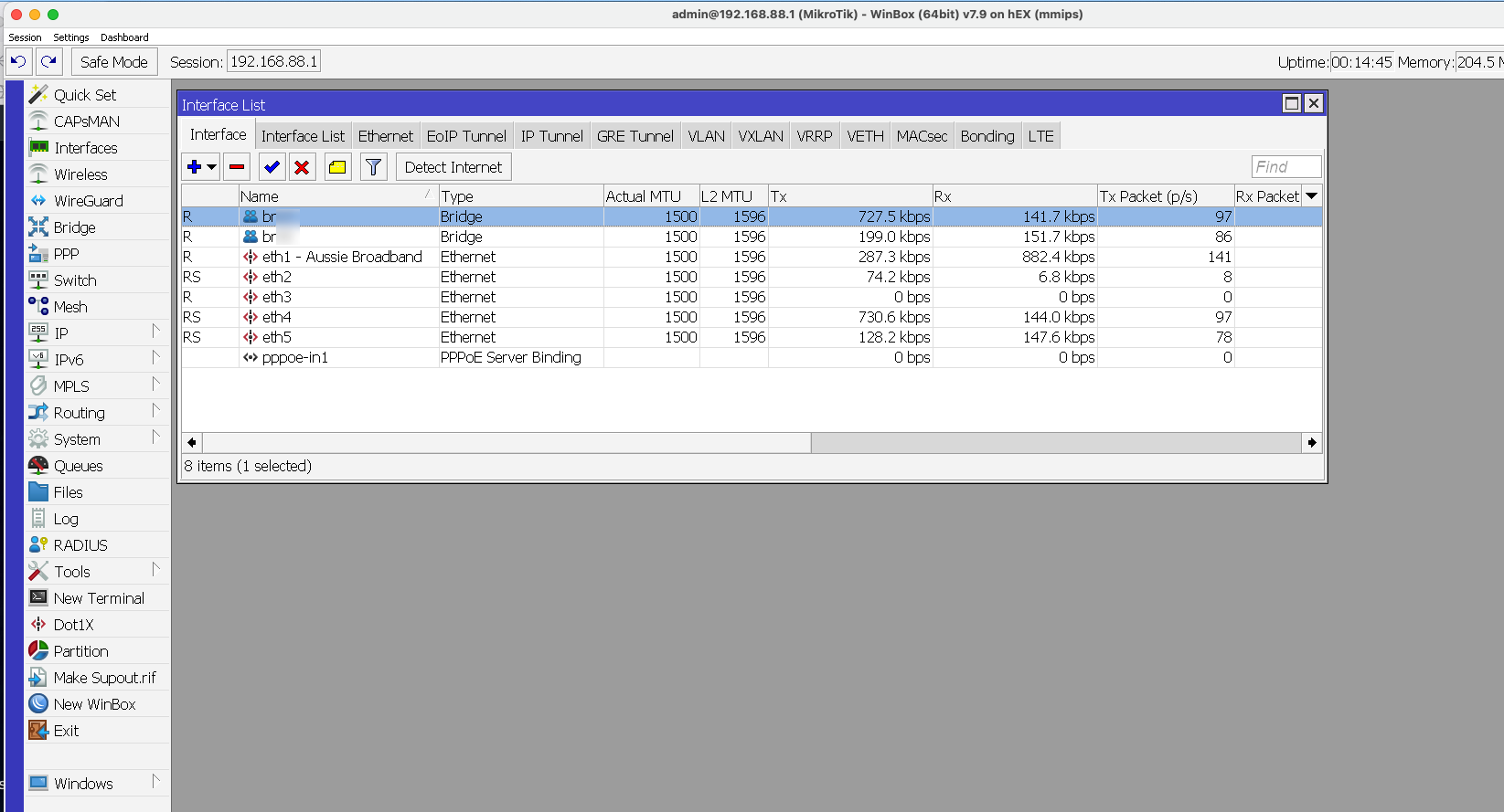
Click on the Interfaces section of the left hand column and you should see the new PPPoE Server Binding that you created in Step 6. You will also see that the Interface that will get the framed route (in my case eth3 - which we configured in Step 5). You can use whichever one you like. As you can see, the other interfaces currently are active and live on my primary IP address. Eth3 is waiting to create the PPPoE connection.
Step 8 - Place the PPPoE interface in the LAN list
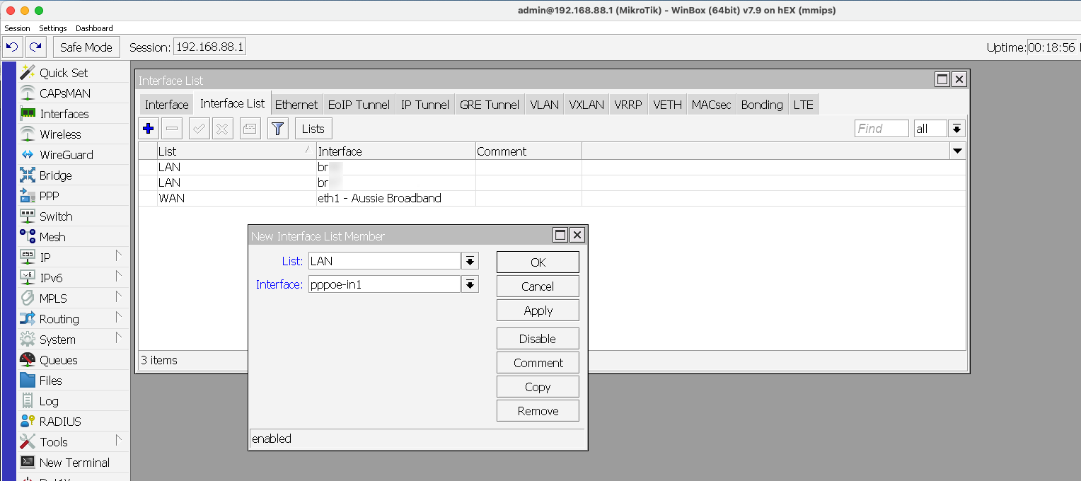
While you are in the Interface section from Step 6, click on the Interface List tab and then add the PPPoE interface to the LAN group. This will make the PPPoE interface go through the routing logic like other interfaces in the LAN group. In the next step we will remove the NATting.
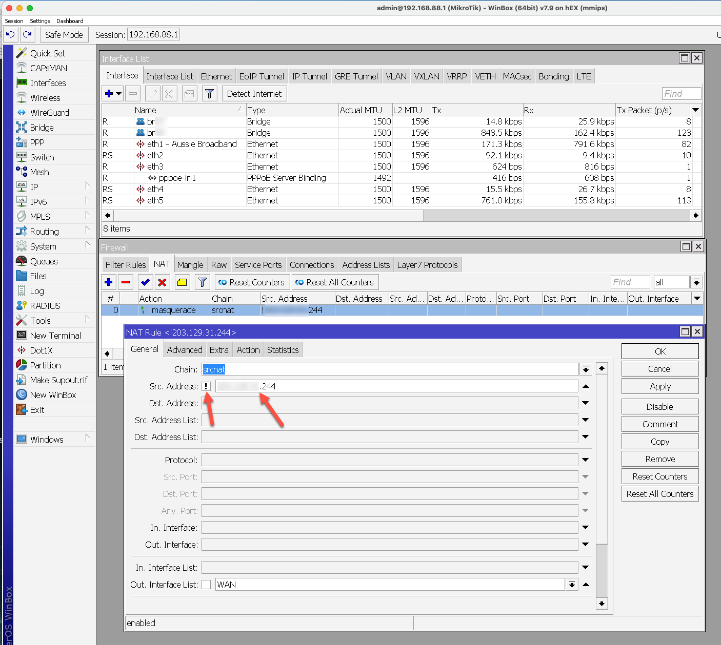
Step 9 - Disable NAT Masquerading for the Frame Routed address
Since the frame routed address is already a public address and since the whole point of this exercise is to avoid "double natting," we will disable masquerading. This is done in the IP -> Firewall section (click on IP then Firewall in the left panel). Then select the NAT tab and there should be a default masquerade action. Double click on it and simply enter your Frame Routed address in the Src. Address section and click on the little box next to it to create an ! mark. This will make masquerading active on everything EXCEPT (that's what the ! does) your Frame Routed address.
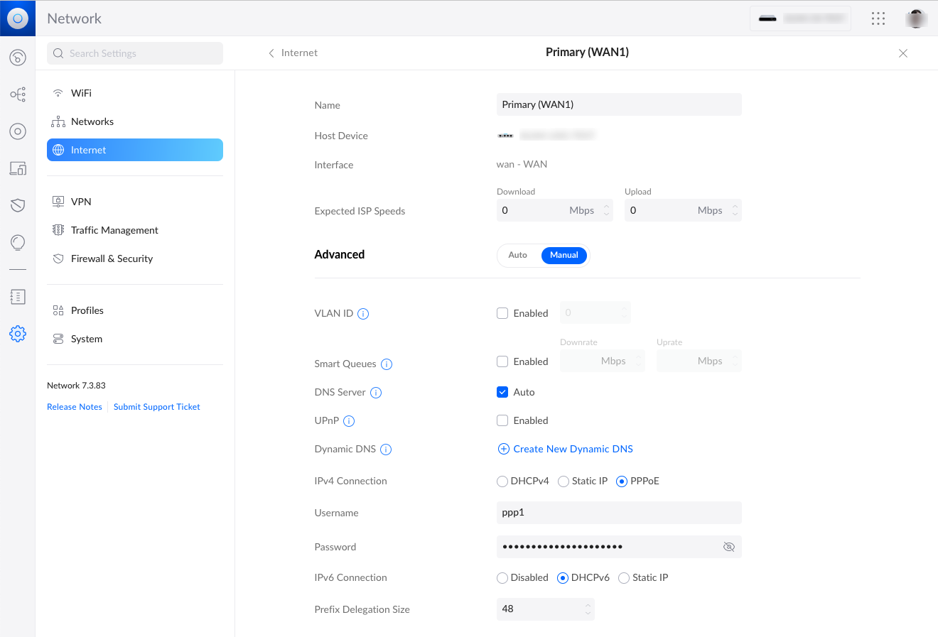
Step 10 - Configure your downstream device to connect via PPPoE
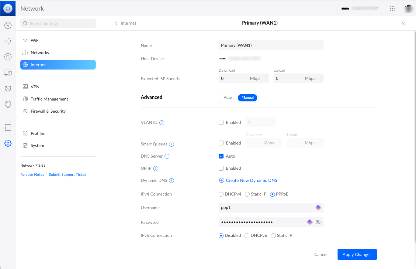
In this example, I have a downstream Ubiquiti Unifi network which is plugged into eth3 on the Mikrotik. From the perspective of the Unifi device, eth3 is the "WAN" connection. We have created our own ISP in a sense. So for this downstream device, it needs to connect to the WAN via PPPoE which is a standard setting on many devices. You can even connect your Mac, Linux or Windows box this way so that it has a public IP address. You can see on the bottom I have the IPv4 connection set as PPPoE and the Username/Password are per what we set up in Step 4 above.
Step 11 - Observe the connected setup
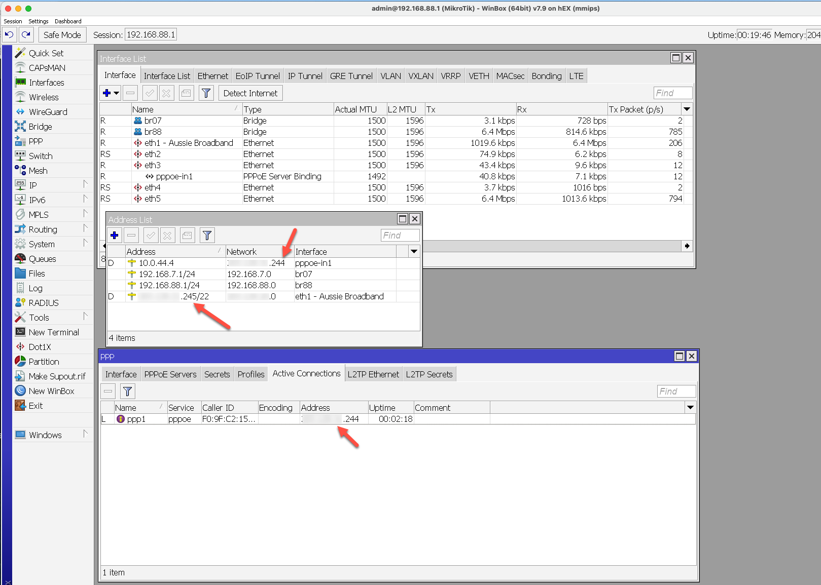
If it all worked you can see evidence of this on the Mikrotik. First, in the interface list, the Ethernet port and PPPoE Server Bidning will have Tx/Rx numbers for the data passing through. If you go to the address list, you will see the PPPoE interface has been added with the frame routed IP address as the Network . You will also see the non-Frame Routed address that you get with DHCP listed under the WAN interface which in my case is eth1. Lastly, if you go to the PPP section and click on the Active Connections tab, you will see the active connection with the Frame Routed address.
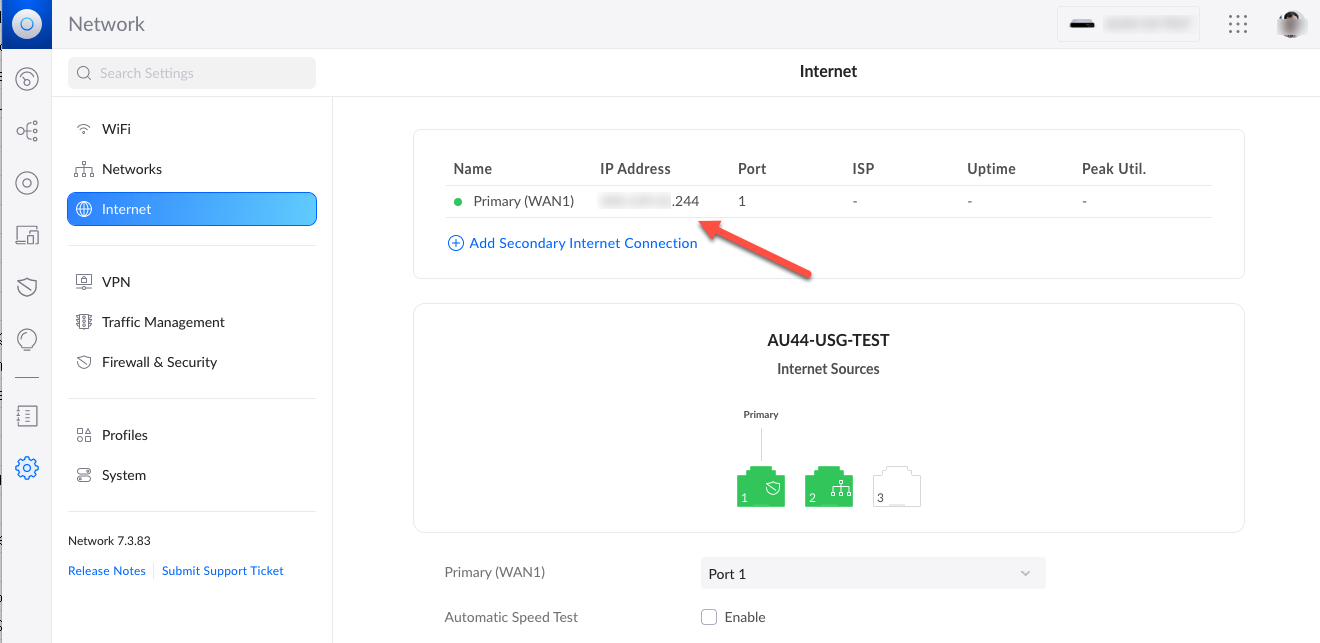
Step 12 - Confirm the connection on the downstream device
You should also be able to see the downstream device recognising the Frame Routed address as its own IP address.
AT THIS POINT YOU ARE BASICALLY DONE, BUT IF YOU WANT TO CONTINUE WITH SETTING UP IPv6, READ FURTHER
Step 13 - Configure IPv6 Client
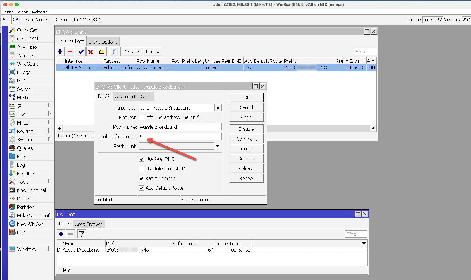
In the IPv6 menu on the left, select DHCPv6 Client. Then add a client on the WAN interface (eth1 in my case) and request "address" and "prefix". You should also provide a Pool Name since this is where the clients in your own network will get their addresses from. VERY IMPORTANT you need to set the Pool Prefix Length here to 64. If you set it to 48 then you will "use up" all your IP addresses with your first DHCPv6 server and won't be able to add another one. In my case, since I'm deliberately running two networks (which is why I have two public IPv4 addresses) I need to be able to delegate two sets of /64 addresses out, one to each network. When you hit OK or Apply you will get your Prefix and Address.
Step 14 - Configure IPv6 Pool
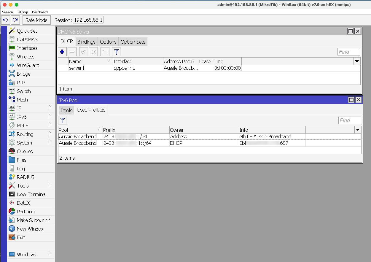
In the IPv6 menu, select IPv6 Pool and add a /64 pool for your downstream network. In Step 13 you would see the /48 prefix you were assigned. To make a /64 just replace 2403:xxxxxx::/48 with 2403:xxxxxx:1::/64 (and 2403:xxxxxx:2::/64, 2403:xxxxxx:3::/64 and so on....)
Step 15 - Configure IPv6 Server
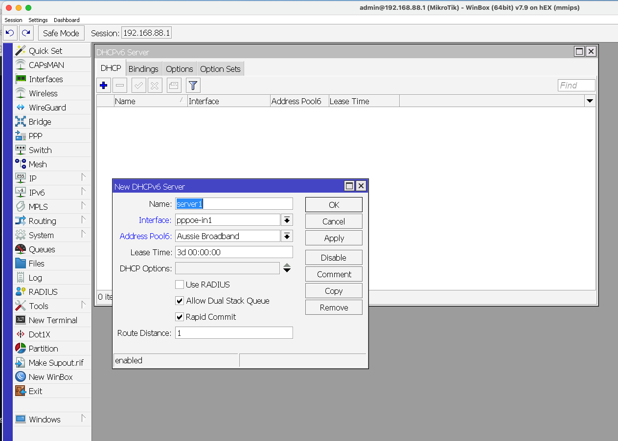
For each network on your LAN you want to set up a new DHCPv6 server. For our first one we will do as in the graphic on the left with the Name, Interface being the PPPoE interface and Pool set as we had done in previous steps.
Step 15a - Configure Neighbor Discovery and IPv6 Route
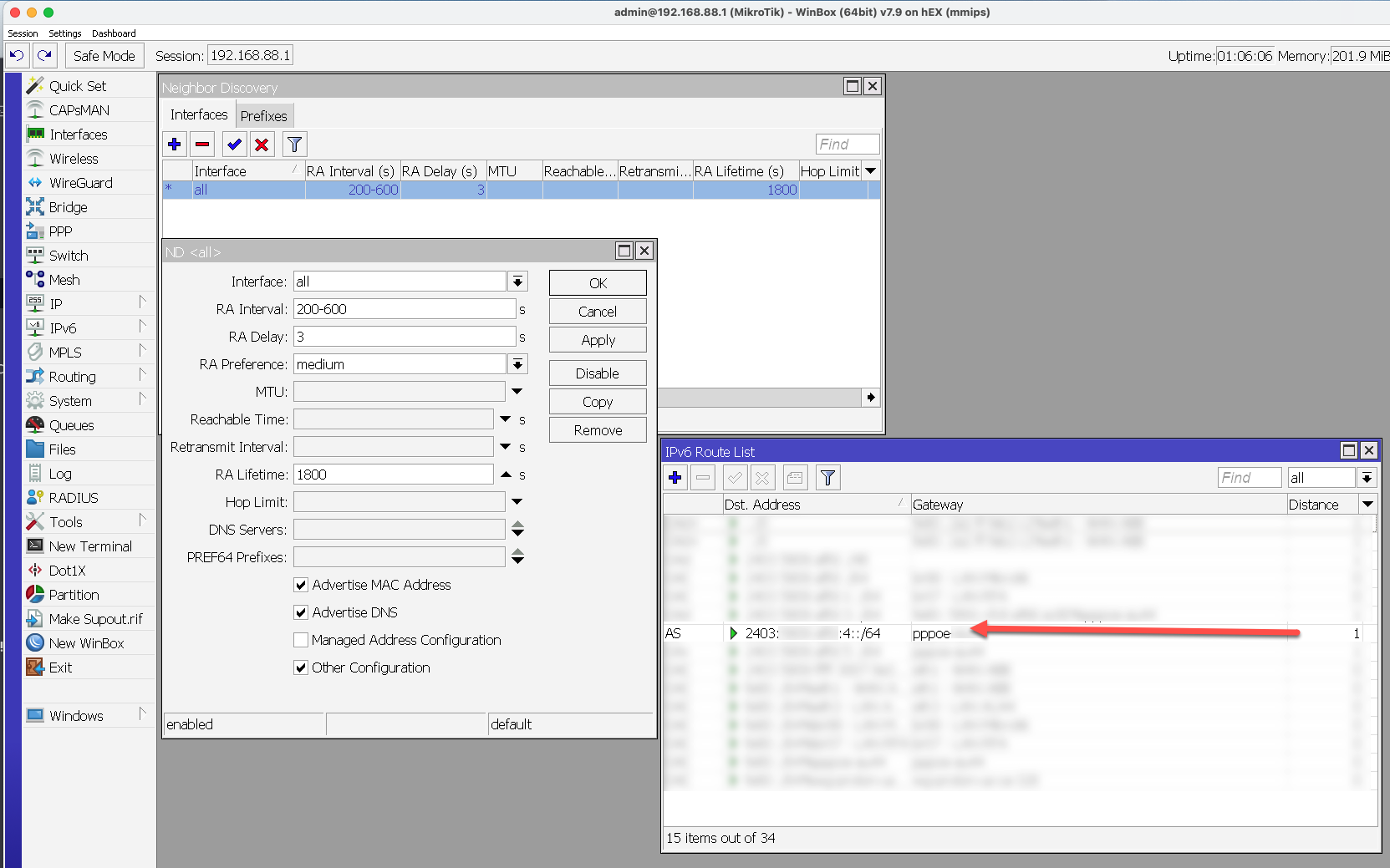
In the IPv6 menu, make sure Neighbor Discovery is on as per the screen shot. Also, depending on how your downstream device is configured, you may need to add a route to the IPv6 route list. Here I have added a route to the pppoe gateway for the 2403:xxxxxx:4::/64 range which I use below in Step 17.
Step 16 - Configure downstream device
You will notice that in addition to the configuration we did in Step 10, we have now added "DHCPv6" as the connection type to get delegated the IPv6 addresses. We also have a point of confusion here for me - someone can maybe send me a comment on why this is, but based on what I've read in the forums, I needed to put Prefix Delegation Size as 48 for this Ubiquiti device, even though it's a 64
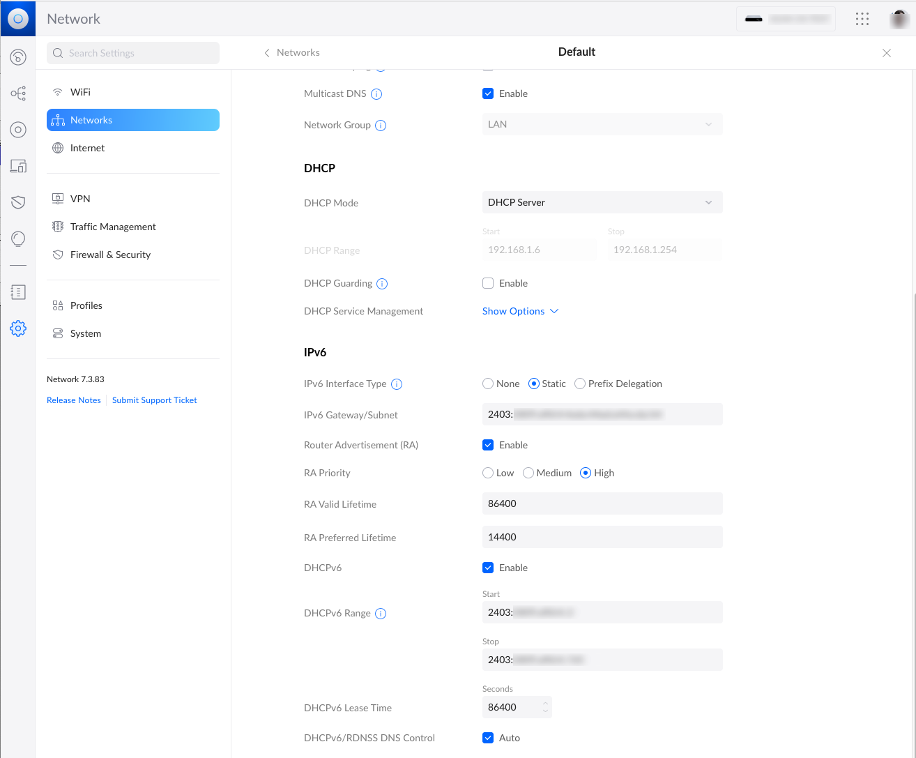
Step 17 - Configure downstream LAN
In order for your downstream router to issue IPv6 addresses to downstream clients, you need to enable IPv6 on the LAN side. Another point of confusion for me - but I would have though the Prefix Delegation setting would work, but on this Ubiquiti Unifi device I need to set it as Static for it to work. Someone who knows why can send me a comment. For IPv6 Gateway/Subnet I selected an unused IPv6 address (one that is not in the pool in Step 14 but within the delegated range). In my case I used 2403:xxxxxx:4::/64 and it seems to work. The DHCPv6 Range was automatically configured by the Unifi device. With this configuration, my downstream clients (for example, a Macbook plugged into the LAN port on the Unifi router) will get an IPv4 address in the range 192.168.1.6-192.168.1.254 (see the DHCP section) and will get several IPv6 addresses in the 2403:xxxxxx:4::/64 range. The Mikrotik seems not to mind this at all even though the other end of the PPPoE connection is 2403:xxxxxx:1::/64.
References
- Whirlpool Thread on using a Framed Route with Mikrotik - this uses a different technique than the one above (using double NATing), but has some good information for a Mikrotik newbie.
- Mikrotik Forum Thread on Framed Route - I couldn't quite follow this thread, it's linked to the Whirlpool thread above and proposes a non Double NAT technique different to mine, but I didn't get it to work.
- Mikrotik Forum Thread on Framed Route that I kicked off - No replies yet, but maybe there is an even better way to do this.
- Mikrotik Forum Thread on IPv6 - I used this information above
- Blog post about IPv6 use on a Ubiquiti router - I used this for configuring the downstream Ubiquiti
- Ubiquiti thread on IPv6 - Ditto
- Mikrotik Config - Great resource with online Mikrotik config tools
Posted: 21-May-2023, Updated: 21-July-2023